Model View
Overview
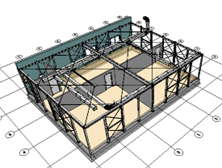
The “Model View” feature in the application allows users to manage and manipulate the visual perspectives of their designs or models. Users can create, save, and switch between different views, such as top view, front view, isometric view, or custom viewpoints, to examine the design from various angles and orientations. This functionality provides flexibility and facilitates a comprehensive understanding of the model, enhancing visualization, analysis, and communication throughout the design process.
Pan model
The “Pan model” command enables users to move the view of the CAD model horizontally or vertically within the workspace without altering its scale or rotation. By using this command, users can shift their viewpoint to focus on different areas of the design while maintaining the same zoom level and orientation. The ability to pan the model enhances navigation, exploration, and precise positioning within the application, providing a convenient way to examine and work on specific regions of interest.
To pan the model in the applicaiton, follow these instructions:
- Position the cursor over the model you want to pan.
- Press and hold the middle mouse button.
- While holding the button, move the mouse in the desired direction.
Rotate model
The “Rotate model” command allows users to manipulate the orientation of the CAD model within the workspace. By using this command, users can rotate the model around point of the mouse, enabling a dynamic view of the design from different angles. The ability to rotate the model enhances visualization, analysis, and understanding of its three-dimensional structure. This command is particularly useful for examining details, evaluating aesthetics, and ensuring proper alignment in the application.
To rotate the model in the applicaiton, follow these instructions:
- Position the cursor over the model you want to rotate.
- Press and hold the right mouse button.
- While holding the button, move the mouse in the desired direction.
Zoom in/out
The “Zoom in/out” command enables users to adjust the magnification level of the 3D model within the view. By using this command, users can increase or decrease the view’s scale, allowing for a closer or more distant perspective on the design. Zooming in provides a detailed view, helpful for examining fine features or working on intricate areas. Conversely, zooming out offers a broader overview, facilitating an understanding of the overall composition or context of the design. The “Zoom in/out” command enhances precision, visibility, and navigation within the application.
To zoom in/out the model in the applicaiton, follow these instructions:
- Position the cursor over the model you want to zoom in/out.
- Wheel up or down the middle button.
Select object
Press the left mouse button on an object in the 3d view.
An object will be selected, and properties will be displayed in the property view.
(see ‘In Property view section)
If you press left mouse button on space, the selection will be released.
Coordinate Values
When the commands require you for a coordinate value (x, y and z) you can respond by pointing in the model window or input coordinate values in the command window.
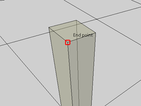
Object snaps
The “Object snaps” feature in the application allows users to precisely locate points or snap to specific geometric elements within a design. By enabling object snaps, users can accurately align objects, draw lines or curves tangent to existing elements, or snap to key points such as endpoints, midpoints, intersections, or center points. This feature enhances precision, efficiency, and consistency in the CAD workflow, ensuring accurate positioning and alignment of objects and facilitating the creation of geometrically accurate designs.
Polar tracking
The “Polar tracking” feature in the application enables users to maintain precise alignment and direction while drawing or modifying objects. With polar tracking enabled, the cursor snaps to specified polar angles or increments as defined by the user. This feature assists in creating lines, arcs, or other elements aligned to specific angles, making it easier to achieve uniformity and alignment in the design. Polar tracking enhances accuracy, efficiency, and consistency in CAD workflows, particularly when working with angular or radial elements.
![]()
Object snap tracking.
The “Object snap tracking” feature in the application allows users to establish temporary alignment paths based on object snaps. When enabled, users can select a reference point and then track along a desired path or direction defined by object snaps. This feature assists in accurately placing or aligning objects relative to existing elements or reference points in the design. Object snap tracking enhances precision, efficiency, and accuracy in CAD workflows by providing visual cues and guidelines for object placement and alignment.
![]()