Section View Command
Overview
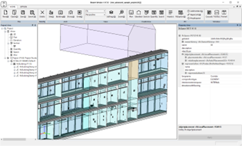
The “Section View” in the application allows users to generate a two-dimensional representation of a design or model by slicing it along a specified plane or section line. By executing the “Section View” command, users can visualize the internal details, cross-sections, or cutaways of the design, providing valuable insights into its composition and construction.
Section views are commonly used in architectural, engineering, and manufacturing disciplines to analyze and communicate the internal structure, components, and relationships within the design. They help in identifying clashes, verifying clearances, evaluating assembly sequences, or understanding complex geometries.
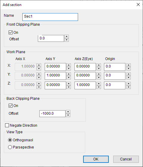
Controls
| Control |
Description |
| Name |
Specify name of the view |
Front Clipping Plane
| Control |
Description |
| On |
Specify to use front clipping palne |
| Offset |
Specify offset value from the clipping plane |
Work Plane
| Control |
Description |
| Axis X |
Is derived by cross product of the Up and the Eye vertices automatically |
| Axis Y |
Specify the Y axis of the Work Plane |
| Axis Z |
Specify the Z axis of the Work Plane |
| Origin |
Specify the origin of the Work Plane |
Back Clipping Plane
| Control |
Description |
| On |
Specify to use front clipping palne |
| Offset |
Specify offset value from the clipping plane |
Other controls
| Control |
Description |
| Negate Direction |
Negate normal vertices of the clipping planes |
| View type |
Specify view projection type (Orthgonal or Parsepective) |