Elavation View Command
Overview
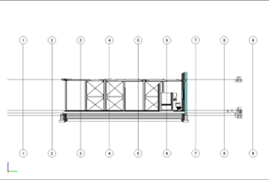
The “Elevation View Command” in the application allows users to generate elevation views of a 3D model or design. By executing this command, users can create two-dimensional representations of the model from specific viewpoints, typically showing the vertical faces or sides of the design.
Controls
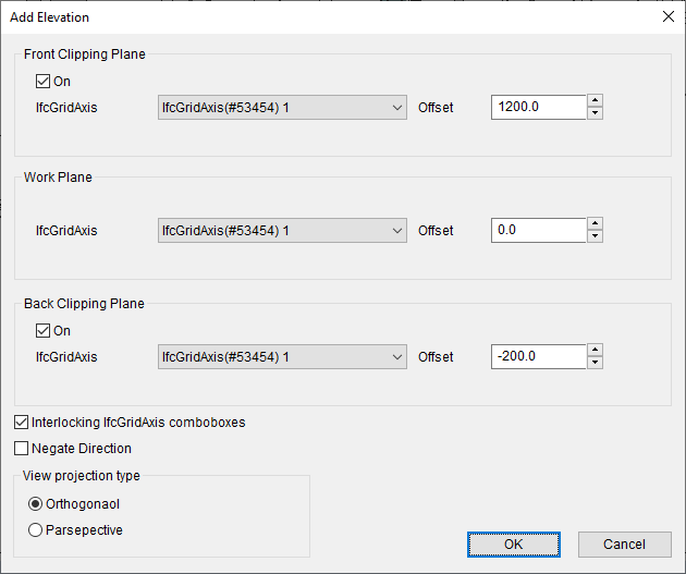
Front Clipping Plane
| Control | Description |
|---|---|
| On | Specify to use front clipping palne |
| IfcGridAxis | Specify a grid line to clip |
| Offset | Specify offset value from the clipping plane |
Work Plane
| Control | Description |
|---|---|
| IfcGridAxis | Specify a grid line for work plane |
| Offset | Specify offset value from the work plane |
Back Clipping Plane
| Control | Description |
|---|---|
| On | Specify to use lower clipping palne |
| IfcGridAxis | Specify a grid line to clip |
| Offset | Specify offset value from the clipping plane |
Other controls
| Control | Description |
|---|---|
| Interlocking IfcBuidlingStorey comboboxes | |
| Negate Direction | Specify to negate or not normal of the clipping planes |
| View projection type | Specify view projection type (Orthgonal or Parsepective) |